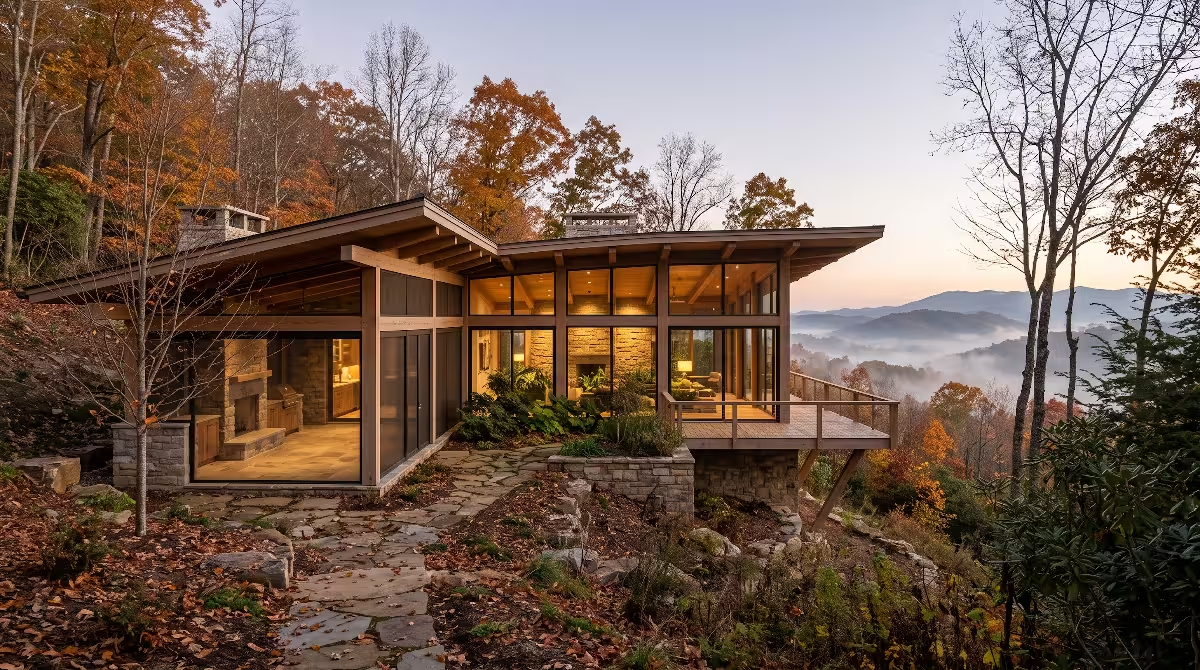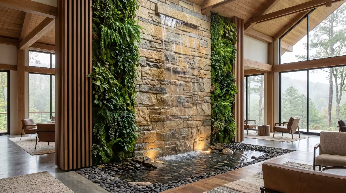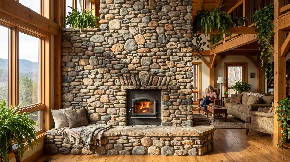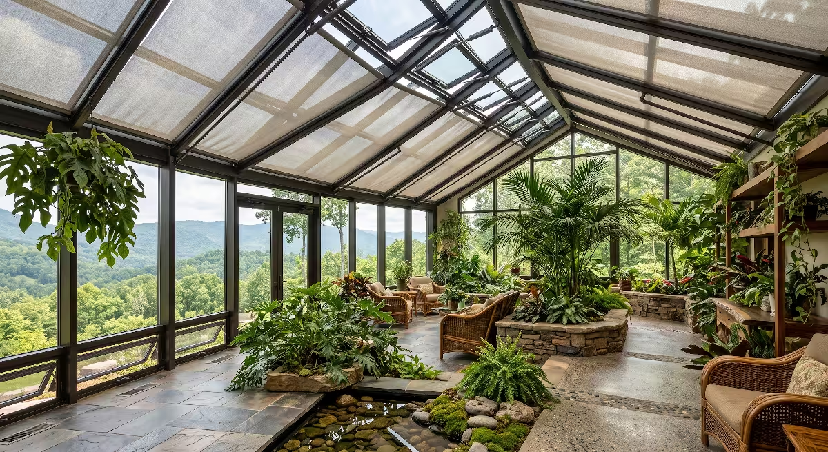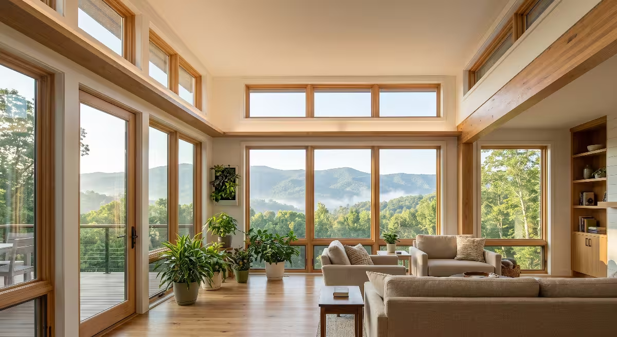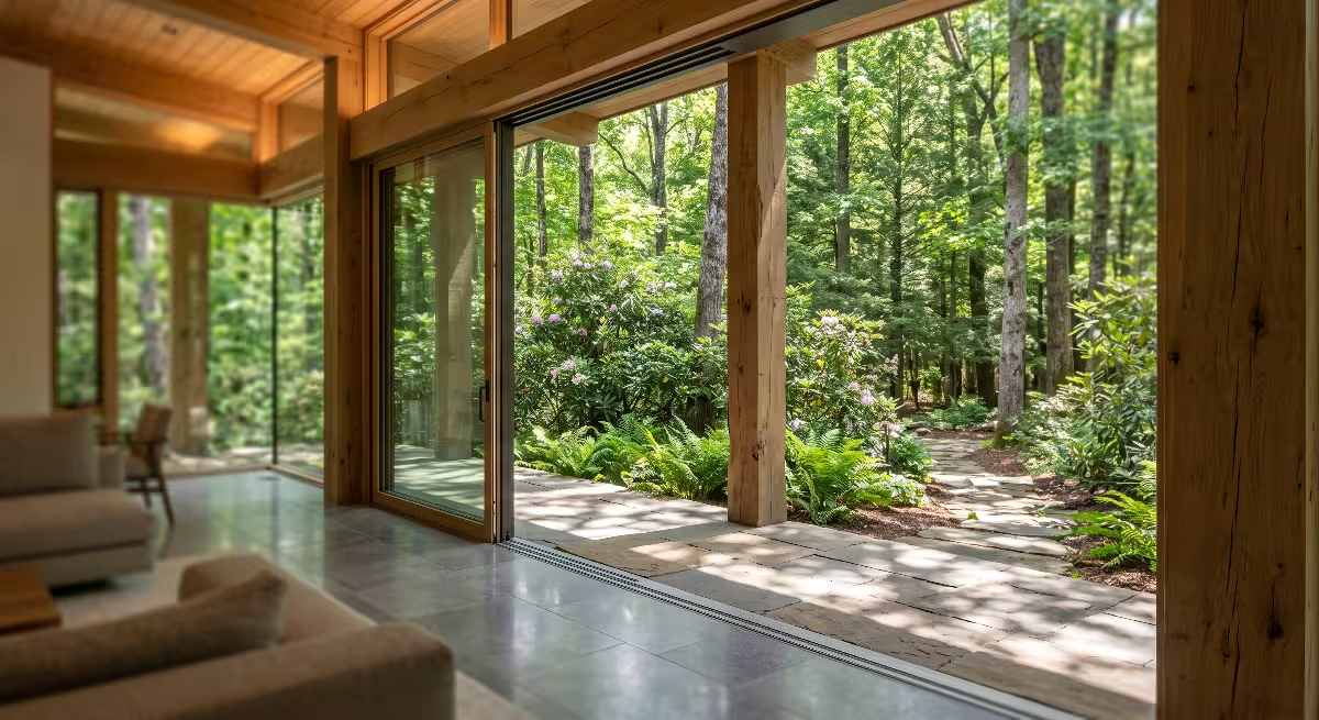


Building a dream home on a steep mountain ridge in Eastern Tennessee is one of the most exciting projects an owner can undertake. Standing on the slopes of Buffalo Mountain or looking out across the Unaka Range near Johnson City, the views are breathtaking. However, building on steep land brings serious engineering hurdles. Traditional home building relies on heavy, bulky framing methods. For decades, builders have used massive amounts of poured concrete and rigid box frames to fight gravity. These old methods force humans to fight the natural landscape. When you fight the mountain, costs rise, soil erodes, and pristine ecosystems suffer permanent damage.
Biophilic engineering offers a smarter path forward. Instead of forcing rigid geometric boxes onto fragile slopes, we can look to biological systems for the answers. Living organisms solved structural mechanics millions of years ago. Nature designs structures that are remarkably light, exceptionally strong, and naturally flexible. In particular, mammalian bone provides a masterclass in handling physical stress. By studying how skeletal frames carry weight, architects and engineers are developing bone-mimic load-bearing structures.
These advanced load-bearing structures adapt to forces rather than simply fighting them. In animal skeletons, material is placed only where physical stress demands it. Empty space is left everywhere else. When we apply this biological logic to residential framing, we unlock radical advantages for hillside construction. We can slash foundation weight, withstand powerful ridge winds, protect mountain water tables, and create interior living spaces that connect deeply with nature. Here is how modern biophilic science turns skeletal biology into the most resilient load-bearing structures ever built for mountain terrain.
The Biology of Load Distribution: What Skeletal Architecture Teaches Mountain Builders
To understand why bone-mimic load-bearing structures perform so well on steep hillsides, we must look closely at human and animal anatomy. Bones are not solid, inert mineral rods. If human bones were completely solid like steel pipes or concrete columns, our bodies would be far too heavy to move. We would collapse under our own deadweight.
Instead, bones are living, dynamic architectural marvels. They combine dense exterior walls with intricate, porous internal networks. This dual design makes bones incredibly light, yet capable of absorbing massive physical shocks. The femur, or thigh bone, supports several times our body weight every time we run or jump. It achieves this feat while remaining hollow and porous across most of its volume.
Traditional home builders often treat residential framing as a brute-force contest. Standard construction codes mandate solid rectangular beams and uniform wooden studs spaced evenly apart, regardless of whether a specific stud carries ten pounds or two thousand pounds. This uniform approach wastes huge amounts of timber, steel, and concrete. In contrast, bone-inspired load-bearing structures place material along exact lines of mechanical force. This creates lighter, stronger residential frames that mirror the elegance of the natural world.
Decoding Wolff’s Law: How Bone Allocates Mass Exactly Where Force Demands It
In the nineteenth century, German anatomist and surgeon Julius Wolff discovered a fundamental rule of biology. Today, we call it
       [External Dynamic Load]
                  │
                  ▼
       [Mechanical Strain Sensed]
                  │
        ┌─────────┴─────────┐
        ▼                   ▼
 [High-Stress Zone]  [Low-Stress Zone]
        │                   │
        ▼                   ▼
 [Deposition of Mass] [Resorption of Mass]
        │                   │
        └─────────┬─────────┘
                  ▼
    [Optimized Load-Bearing Structures]
Wolff’s Law provides a perfect blueprint for high-efficiency load-bearing structures in residential architecture. In standard home construction, an engineer specifies identical wooden joists or steel beams across an entire floor span. This means that areas near the center of the span carry heavy bending stress, while areas near the end supports experience completely different shearing forces. Yet, conventional builders use the exact same solid rectangular profile across the entire length.
By applying Wolff’s Law through modern structural software, engineers can design customized load-bearing structures that mimic this biological adaptation. Beams and structural columns become thicker and denser at connection joints where bending moments peak. At the same time, the same members taper into slender, open geometries in low-stress zones. Material is never wasted. By placing structural mass strictly where the physical forces travel, homes built with these load-bearing structures use significantly less raw material while delivering superior structural performance on steep mountain grades.
Cortical and Trabecular Duality: Engineering High-Performance Porosity
When you slice open a long bone such as the human femur, you immediately observe two distinct types of tissue working together in seamless harmony:
- Cortical Bone: The hard, dense outer shell that resists bending, torsion, and external impact.
- Trabecular Bone: The spongy, porous interior lattice that redirects multidirectional stress vectors.
  ===========================================  <- Dense Cortical Shell
  |  /\    / \    /\    / \    /\    / \    |     (Resists Bending & Shear)
  | /  \  /   \  /  \  /   \  /  \  /   \   |
  |/____\/_____\/____\/_____\/____\/_____\  |  <- Open Trabecular Lattice
  |\    /\     /\    /\     /\    /\     /  |     (Diffuses Multi-Axis Loads)
  | \  /  \   /  \  /  \   /  \  /  \   /   |
  |  \/    \ /    \/    \ /    \/    \ /    |
  ===========================================  <- Dense Cortical Shell
Cortical bone forms the dense outer surface. It is tightly packed, rigid, and designed to shield the internal marrow while resisting heavy bending and twisting forces. It provides the primary perimeter defense against external loads.
Directly inside this dense outer wall lies trabecular bone, also known as cancellous or spongy bone. Despite its name, trabecular bone is not soft like a kitchen sponge. It is a three-dimensional lattice of tiny bony plates, struts, and arches called trabeculae. These microscopic struts do not run in random directions. They align precisely along the lines of principal stress within the body.
Modern load-bearing structures can mimic this cortical and trabecular duality to achieve structural efficiency. The exterior of a residential framing member acts as the cortical shell, resisting weathering, surface impacts, and direct compression. Inside that shell, generative design programs generate an open, porous web of struts that mimic trabecular lattices.
These porous load-bearing structures absorb and redirect complex forces across hundreds of interconnected micro-struts. If an unexpected force strikes one side of the house, the internal lattice disperses the energy throughout the entire frame rather than concentrating the stress at a single fragile joint. This open-cell geometry yields load-bearing structures that are up to 40 percent lighter than solid beams while providing exceptional rigidity against shifting mountain winds.
The 1866 Culmann Crane Paradigm: From Femoral Neck to Architectural Cantilever
The historical bridge connecting bone biology with modern structural engineering began in 1866 in Zurich, Switzerland. Swiss engineer Karl Culmann was studying the design of large industrial cranes used to hoist heavy loads. At the same time, anatomist Georg Hermann von Meyer was presenting drawings of the internal trabecular patterns found inside the head and neck of the human femur.
When Culmann examined Meyer’s anatomical sketches, he experienced an epiphany. He noticed that the crisscrossing lines of tiny bony struts inside the femoral neck matched the theoretical stress trajectories he had calculated for curved iron cranes. The human femur was essentially a curved, cantilevered crane engineered by millions of years of evolution. The bone had independently discovered how to route tension and compression along curved, intersecting trajectories to prevent the neck from snapping off under the weight of the human torso.
Culmann’s discovery proved that natural biology and mathematical engineering share the same underlying truths. Today, this connection is critical for custom mountain architecture. Mountain homes frequently rely on deep cantilevers. Homeowners want living rooms, observation decks, and primary suites that project outward past the foundation edge, floating dramatically above the trees.
Traditional cantilevers require heavy, solid steel I-beams that add immense deadweight to the foundation. By returning to Culmann’s principles, modern engineers can model cantilevered load-bearing structures directly on the femoral neck. Using curved, lattice-filled framing arms, these specialized load-bearing structures transfer heavy downward loads back into the mountain slope smoothly, eliminating sharp stress concentrations and keeping the home securely anchored above the valley floor.
Solving the Mountain Foundation Dilemma: Steep Slopes Without Mass Concrete
Building on the rolling, ancient topography of the Appalachian mountains requires respect for the land. In Northeast Tennessee, pristine building lots often feature slopes ranging from 20 degrees to over 45 degrees. Conventional building methods handle these dramatic grades through pure brute force. Developers bring in heavy bulldozers, blast through bedrock, excavate thousands of tons of earth, and pour towering, monolithic concrete retaining walls.
These conventional building practices cause severe ecological and structural problems. Heavy excavation destabilizes the natural slope equilibrium. It strips away topsoil, accelerates soil erosion, and cuts off underground water paths.
Furthermore, towering concrete retaining walls act as massive, impermeable dams on the hillside. When seasonal rains sweep through the mountains, hydraulic pressure builds behind these solid walls. Over time, that hydrostatic pressure causes cracking, shifting, and even catastrophic foundation failure.
Bone-mimic load-bearing structures offer a far superior, low-impact solution for hillside foundations. By adopting the mechanics of animal joints, skeletal root systems, and cellular bones, architects can anchor homes securely to steep mountain grades without tearing the mountain apart.
The Failure of Monolithic Concrete Retaining Walls on Fragile Ridges
To understand why custom mountain homes need alternative foundation systems, we must look at the mechanical weaknesses of traditional concrete retaining walls. Concrete is outstanding in compression, meaning it can support heavy downward weight. However, standard concrete performs poorly in tension and shear. When a builder pours a thirty-foot-tall concrete foundation wall into a cut hillside, that wall must constantly push back against thousands of tons of wet mountain soil trying to slide downward.
       TRADITIONAL FOUNDATION                   BONE-MIMIC MICRO-PILE FOUNDATION
    (Monolithic / High Disturbance)                (Porous / Low Disturbance)

  Downhill                     Uphill          Downhill                     Uphill
    Slope                       Slope            Slope                       Slope
     \                            /               \                            /
      \    ┌──────────────┐      /                 \    [Lightweight Home]    /
       \   │ Heavy Solid  │◄────Hydrostatic         \     │     │     │      /
        \  │ Concrete     │     Pressure             \   (O)   (O)   (O)    /
         \ │ Retaining    │     (Trapped              \   │ \   │   / │    /
          \│ Wall         │      Water)                \  │  \  │  /  │   /
           └──────────────┘                             \ │   \ │ /   │  /
             ▲          ▲                                \│    \│/    │ /
             └──Wet Bedrock                               ├───Bedrock───┤
              (High Shear Risk)                          (Multi-Angle Pins)
As water saturates the soil during heavy rainfall, hydrostatic pressure behind the wall spikes dramatically. If the drainage pipes behind the concrete become clogged with silt or tree roots, that trapped water creates immense lateral pressure. The wall begins to tilt forward, developing hairline fractures that slowly expand through seasonal freeze-thaw cycles.
Eventually, the connection between the solid foundation and the bedrock weakens. Fixing a failing concrete retaining wall on a steep mountain ridge costs hundreds of thousands of dollars and often requires invasive soil nailing and chemical grout injections.
Traditional monolithic foundations also create a severe weight problem. Concrete weighs roughly 150 pounds per cubic foot. Pouring hundreds of yards of concrete creates an enormous deadweight that presses down on fragile slope shear planes.
In contrast, bone-mimic load-bearing structures rely on distributed support networks rather than singular, monolithic mass. Instead of resisting earth pressure with deadweight, these advanced load-bearing structures use lightweight skeletal footings that touch the earth lightly, dramatically reducing the total mass resting on the slope.
Branched Trabecular Pier Assemblies: Anchoring into Bedrock Like Tendon to Bone
How does nature anchor flexible, dynamic tissues into rigid, mineralized surfaces? In the human body, tendons must connect soft muscles directly to hard bones. If this transition were abrupt, the tendon would shear off under intense physical exertion. Nature solves this problem through entheses: specialized biological transition zones that gradually shift from soft collagen fibers, to mineralized fibrocartilage, to dense cortical bone. The connection branches out into microscopic rootlets that embed deep into the bone matrix.
Architects use this identical principle to anchor bone-mimic load-bearing structures into mountain slopes. Instead of pouring a continuous concrete wall, engineers install branched pier assemblies that mimic these natural entheses.
- Drilled Micro-Piles: Small, high-strength steel pins are drilled at multiple divergent angles directly into the mountain bedrock.
- Multi-Angle Geometry: Like tree roots or skeletal fibers, these micro-piles spread outward in three dimensions, interlocking with the subterranean stone.
- Porous Pile Caps: Generatively designed concrete caps sit on top of the micro-pile clusters, mimicking the spongy structure of trabecular bone.
- Flexible Articulation: The load-bearing structures of the home connect to these caps through semi-flexible, moment-resisting joints that allow microscopic movement without cracking.
When wind or gravity pulls on the house, forces travel down into these branched load-bearing structures. Instead of focusing the load onto a single flat foundation seam, the multi-angle micro-piles distribute tension and compression deep into the rock mass. The home becomes an organic extension of the mountain bedrock, held firmly in place by tensile root systems rather than brute deadweight.
Preserving Subsurface Hydrology and Existing Root Ecosystems
The Appalachian temperate rainforest is one of the most biodiverse ecosystems in the world. Old-growth oak, hickory, and tulip poplar trees stabilize mountain slopes with vast, interconnected root systems. Beneath the forest floor, natural subsurface hydrology channels rainwater through underground springs, soil macropores, and weathered rock fissures.
When a builder excavates a hillside for a traditional concrete foundation, they sever these ancient root networks. Surrounding mature trees die within two to three years due to root damage and altered water availability.
Worse, the solid concrete wall dams the natural subsurface flow. Water pools uphill from the structure, saturating the soil and triggering landslides along adjacent slope contours.
Bone-mimic load-bearing structures eliminate these ecological disasters:
- Minimal Soil Disturbance: Branched pier systems require only small, targeted drill holes, preserving up to 90 percent of the natural ground surface.
- Intact Root Systems: Heavy equipment does not need to strip the hillside bare, allowing mature trees to keep their stabilizing root networks intact right up to the building perimeter.
- Uninterrupted Hydrology: Rainwater flows naturally around the slender, isolated piers, running down the mountain through existing channels without building hydrostatic pressure.
- Protection of Downhill Slopes: By eliminating the damming effect, these load-bearing structures prevent soil saturation, protecting downstream properties and natural stream ecosystems from sediment runoff.
Structural Performance Under Extreme Appalachian Ridge Conditions
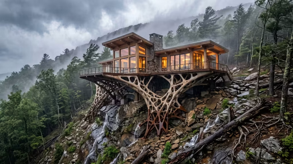
Building a home on an exposed Appalachian ridge means confronting dynamic environmental loads. While valley homes enjoy natural shelter from surrounding hills, homes perched on ridge tops face fierce meteorological and geological forces.
High winds sweep up mountain hollows, compressing as they reach the crest to create severe aerodynamic uplift and lateral shear. At the same time, regional seismic activity in the Southern Appalachians introduces periodic ground vibrations that can crack rigid building frames.
Standard home construction treats these external forces as secondary considerations, relying on nailed plywood sheathing and metal strapping to resist lateral loads. However, bone-mimic load-bearing structures integrate dynamic resistance directly into their primary geometries. By understanding how skeletal systems deflect, absorb, and channel multi-axis loads, biophilic engineers create mountain residences with unmatched structural resilience.
Managing Turbulent Wind Shear and Multidirectional Uplift via Porous Lattices
Wind behaving on a mountain ridge is fundamentally different from wind in flat coastal plains. As air strikes a steep mountainside, it is forced rapidly upward in a phenomenon known as topographic wind speed-up. When this accelerated airflow reaches the ridge crest, it detaches from the ground, creating violent, turbulent eddies and powerful vertical uplift.
       TURBULENT WIND FLOW OVER EXPOSED RIDGE

                     ▲ Uplift Vortex
                    / \
       Turbulent   /   \
       Wind       /  [Bone-Mimic Lattice]
       ──────────►  (Air flows through and
       ──────────►   dissipates dynamically)
                     \   /
                      \ /
     Ridge Crest       ▼
    ════════════════════════════════════════════════
    ////////////////////////////////////////////////
Traditional homes present large, solid, flat surfaces to these wind vectors. A conventional wall or roof overhang acts like a giant sail. When heavy gusts hit the structure, massive positive pressure pushes on the windward side, while intense negative suction pulls on the leeward roof surfaces. This uneven pressure rips away eaves, shears structural fasteners, and twists conventional load-bearing structures out of square.
Bone-mimic load-bearing structures handle turbulent wind through controlled porosity and streamlined curves:
- Aerodynamic Outer Envelopes: Rather than presenting flat vertical walls, bone-inspired homes use rounded, organic contours modeled after bird skulls and sea shells. These curves allow high-velocity winds to flow smoothly around the building envelope.
- Porous Screen Lattices: Exterior porches, cantilevered decks, and roof overhangs are built using open-cell trabecular geometries. Wind flows through these porous load-bearing structures rather than slamming into a solid barrier.
- Vortex Dissipation: As air passes through the microscopic and macroscopic voids of the lattice, the turbulent energy breaks down into thousands of harmless micro-vortices. This eliminates dangerous uplift forces and keeps cantilevered decks anchored during severe mountain thunderstorms.
Seismic Wave Attenuation: Micro-Flexure in the East Tennessee Seismic Zone
Many homeowners are surprised to learn that Eastern Tennessee lies within the East Tennessee Seismic Zone (ETSZ). This active geological belt stretches across Northeast Tennessee, Northwest Georgia, and Northeast Alabama. The ETSZ produces hundreds of small earthquakes every year, with the potential for moderate to severe seismic events that could shake regional ridgelines.
                  EARTHQUAKE WAVE PROPAGATION

   [Seismic Shear Wave (S-Wave)] ──► ──► ──►
               │
               ▼
   [Branched Bedrock Anchors]
               │
               ▼
   [Trabecular Damping Nodes] (Micro-flexure absorbs kinetic energy)
               │
               ▼
   [Living Spaces Remain Stable and Isolated]
When an earthquake strikes, it sends horizontal shear waves (S-waves) rippling through the Earth’s crust. Solid, brittle structures made of unreinforced masonry or rigid, unyielding concrete perform poorly during earthquakes. They cannot flex without cracking. When ground accelerations exceed the tensile limits of the material, rigid load-bearing structures fail catastrophically.
Living bone handles seismic shocks through internal friction and micro-flexural compliance. The microscopic trabeculae inside cancellous bone can bend slightly under high impact, absorbing kinetic energy and dissipating it as harmless thermal energy before micro-cracks can grow into structural fractures.
Biophilic load-bearing structures mirror this seismic damping:
- Anisotropic Joint Design: Structural joints are engineered with varying degrees of stiffness along different axes, matching the natural shock-absorbing qualities of animal joints.
- Dissipative Internal Geometry: Within the frame, trabecular members can flex microscopically during horizontal ground shaking.
- Harmonic Decoupling: The complex, variable density of bone-inspired load-bearing structures prevents the entire building from vibrating at a single resonant frequency. Instead of amplifying seismic waves, the frame scatters the energy across multiple dimensional paths, protecting the home from structural collapse.
Deflection Control and Cantilever Reach Over Steep Embankments
One of the greatest joys of custom mountain living is stepping out onto a cantilevered terrace that floats high above the forest floor. However, deep cantilevers present major structural engineering challenges. As a balcony or room projects further out from its primary supports, the downward bending force (deflection) increases exponentially.
In traditional construction, controlling deflection requires massive steel beams with tall, solid web profiles. These heavy beams add enormous deadweight to the foundation. Furthermore, solid steel beams expand and contract significantly with changing seasonal temperatures, causing creaking sounds and cracking interior drywall.
Bone-mimic load-bearing structures solve deflection challenges through optimized material distribution:
  Traditional Solid Cantilever:
  [Heavy Solid Steel Beam] ========================  (Massive deadweight, high sag)

  Bone-Mimic Optimized Cantilever:
  [Deep Trabecular Truss]  \  /  \  /  \  /  \  /   (Tapered profile, zero excess mass,
                           \/    \/    \/    \/      maximum stiffness at the root)
Bone-inspired cantilevers mimic the structural design of the avian wing bone or the human pelvis. The framing assembly is deep and wide at the foundation wall where bending moments are highest, providing maximum leverage and resistance to rotational sag. As the cantilever extends outward over the slope, the structure tapers smoothly into a lightweight, open-cell profile.
By eliminating deadweight at the outer tip of the cantilever, the overall bending strain is slashed by more than 50 percent. This allows homeowners to achieve dramatic cantilever projections over steep embankments without installing intrusive ground pillars that disrupt downhill views.
Modern Fabrication: Turning Bone Morphometry into Residential Realities
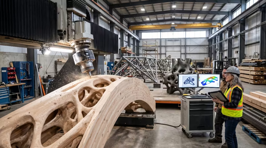
For centuries, designing buildings that mirrored the complex, curved shapes of human anatomy was practically impossible. Traditional construction relies on straight lines, 90-degree angles, and flat planes because standard sawmills, brick factories, and welding shops are set up to produce uniform, modular components. Hand-carving curved, organic load-bearing structures was far too slow, expensive, and structurally unpredictable for residential projects.
The digital design revolution has changed construction permanently. Today, high-speed computers, advanced biological algorithms, and multi-axis digital manufacturing tools allow us to build complex, bone-inspired load-bearing structures with microscopic accuracy.
Architects can now analyze structural forces inside custom software, generate optimized biological geometries, and send the digital blueprints directly to robotic fabrication machines. This direct digital workflow turns the structural logic of skeletal biology into practical, affordable realities for custom mountain homes.
Topology Optimization and Generative FEA Modeling
The foundation of modern biomimetic engineering is a computational technique called Finite Element Analysis (FEA), paired with Topology Optimization algorithms. Instead of drawing a building frame by hand, an engineer inputs the project’s specific constraints into a generative design program:
- Digital Boundary Modeling: The engineer defines the home’s layout, foundation connection points, and architectural living volumes.
- Environmental Load Mapping: The software applies simulated environmental loads, including local wind speeds, snow accumulation, seismic accelerations, and live occupant weights.
- Bi-directional Evolutionary Structural Optimization (BESO): The computer runs an iterative algorithm that mimics natural evolution. It applies the forces to a solid virtual block of material, analyzes where physical stress concentrates, and systematically erases material from low-stress zones.
- Stress Alignment Validation: Like bone remodeling under Wolff’s Law, the virtual material thickens along high-stress paths, generating complex, organic branching webs.
       [Solid Digital Design Space]
                    │
                    ▼
     [Apply Wind, Gravity & Seismic Loads]
                    │
                    ▼
     [FEA Calculates Stress Concentrations]
                    │
                    ▼
    [BESO Removes Underutilized Material]
                    │
                    ▼
   [Iterative Growth Along Stress Lines]
                    │
                    ▼
 [Optimized Bone-Mimic Structural Geometry]
The resulting structural model does not look like a traditional assembly of 2×6 studs or rectangular steel posts. It looks like an intricate, sculpted bone frame. Every single strut, hollow chamber, and curving node corresponds to an exact force vector.
By using topology optimization, engineers can eliminate between 30 and 50 percent of the material required by conventional framing while producing load-bearing structures that are demonstrably stiffer and more resilient under dynamic mountain storms.
Mass Timber and CNC Glulam Trabecular Bents
Once computer algorithms generate an optimized bone-mimic structural frame, that frame must be fabricated using sustainable, high-performance materials. In the forested mountains of East Tennessee, mass timber is the premier material for biophilic load-bearing structures.
Mass timber relies on thick, laminated layers of wood glued or fastened together to form massive, fire-resistant structural elements. To produce bone-mimic forms, fabricators use multi-axis Computer Numerical Control (CNC) robotic milling machines. These giant robotic arms can carve curved Glue-Laminated timber (Glulam) beams with millimeter precision.
  TRADITIONAL POST-AND-BEAM                   BONE-MIMIC CNC GLULAM BENT
     (Sharp 90-Degree Joints)                    (Continuous Organic Arches)

       ┌────────────────────┐                          .---""""---.
       │  Rigid Cross Beam  │                        /   Trabecular \
       └─────────┬──────────┘                       /     Branching  \
                 │                                 |     .--------.   |
                 │ Stress Point                    |    /          \  |
            ┌────┴────┐                            |   |   Living   | |
            │ Column  │                            |   |   Space    | |
            └─────────┘                            |   |            | |
Architects use these tools to build Glulam bents: continuous structural ribs that curve smoothly from the foundation piers all the way up through the walls and roofline. In conventional framing, walls and roofs meet at sharp 90-degree corners, creating severe stress concentrations where joints can tear apart in high winds.
In contrast, bone-mimic timber bents sweep across corners in broad, continuous arches that mimic the pelvic girdle or the ribcage of large mammals. These sweeping curves eliminate joint failure points, distribute gravity loads smoothly into the earth, and bring the warm, tactile, biophilic beauty of natural wood directly into the home’s interior design.
3D-Printed UHPC Foundations and Prefabricated Cold-Formed Steel Assemblies
For foundation systems and long-span interior trusses, two advanced manufacturing technologies are driving the adoption of bone-mimic load-bearing structures:
3D-Printed Ultra-High Performance Concrete (UHPC)
Conventional concrete requires wooden or foam forms to hold the wet slurry in place, limiting builders to simple rectangular walls and round columns. Today, robotic 3D-printing systems can extrude specialized Ultra-High Performance Concrete layer by layer without any formwork. UHPC contains microscopic fibers and reactive silica that give it five times the compressive strength of regular concrete, along with remarkable tensile ductility.
On steep mountain sites, robotic printers can lay down foundation piers that mimic the internal cellular structure of trabecular bone. The printer deposits dense concrete along the exterior perimeter to form a protective cortical shell, while printing open, hollow, honeycomb geometries on the interior. These 3D-printed load-bearing structures slash concrete consumption by more than half, drastically reduce heavy mixer truck deliveries on winding mountain roads, and produce footings engineered specifically for local soil conditions.
Prefabricated Cold-Formed Steel (CFS) Lattices
For framing interior walls, roof trusses, and cantilevers,
Using generative design files, fabricators can assemble modular CFS panels containing internal diagonal webs that mimic the crisscrossing struts inside animal bones. Because CFS is lightweight, entire roof trusses and wall sections can be prefabricated off-site in climate-controlled factories, transported to tight mountain ridge building sites, and flown into place with light cranes in a fraction of the time required for traditional stick-framing.
Biophilic Value: The Psychological Impact of Organic Structural Forms
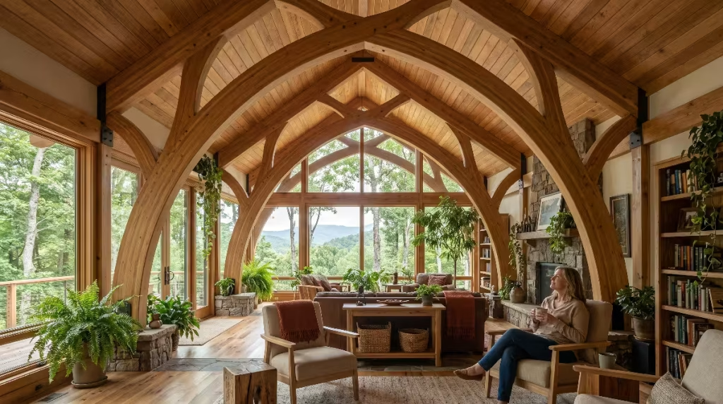
Biophilic design is rooted in a simple, profound scientific truth: human beings possess an innate, genetically encoded affinity for the natural world. For 99 percent of human history, our ancestors lived, hunted, and found shelter within organic, evolving ecosystems. Our visual, nervous, and cognitive systems evolved to interpret natural shapes, fractal patterns, and living materials.
Over the past century, industrial home building abandoned these biological truths in favor of harsh, sterile boxes. Modern suburban homes are filled with flat drywall planes, sharp 90-degree corners, and artificial plastic finishes. Environmental psychology studies demonstrate that living inside sterile, unnatural environments increases resting cortisol levels, elevates blood pressure, and contributes to mental fatigue.
Bone-mimic load-bearing structures provide a revolutionary opportunity to reconnect our homes with the healing patterns of nature. When the primary load-bearing structures of a residence mirror biological anatomy, structural engineering becomes an immersive biophilic experience. The home stops feeling like a synthetic, artificial box dropped onto the hillside. Instead, it feels like a protective, living organism that grew naturally out of the mountain terrain.
Visual Connection with Nature (Pattern 1 of Biophilic Design)
In the renowned 14 Patterns of Biophilic Design published by environmental consulting firm Terrapin Bright Green, Pattern 1 is the Visual Connection with Nature. This pattern emphasizes that providing views of natural elements, organic systems, and living processes measurably reduces stress, improves cognitive focus, and enhances overall emotional well-being.
       [Rigid Conventional Box]                [Bone-Mimic Biophilic Frame]
    (Flat Planes, Sharp Corners)            (Curved Bents, Organic Flow)
                 │                                        │
                 ▼                                        ▼
    [Visual Monotony & Fatigue]               [Fractal Fluency & Calm]
                 │                                        │
                 ▼                                        ▼
    [Elevated Physiological Stress]           [Reduced Cortisol & Heart Rate]
Most builders attempt to achieve this pattern simply by installing large glass windows looking out at mountain trees. While scenic window views are wonderful, bone-mimic load-bearing structures bring the visual connection with nature directly into the structural bones of the home:
- Biomorphic Forms and Patterns (Pattern 8): The gentle, flowing curves of CNC-milled glulam arches, branching column capitals, and trabecular truss networks directly reflect biological forms.
- Fractal Geometry: Skeletal load-bearing structures naturally incorporate fractal patterns, repeating similar geometric structures across multiple scales, from large primary arches down to small lattice struts.
- Visual Softness: By replacing harsh 90-degree wall and ceiling intersections with continuous anatomical curves, the visual environment feels gentler on the human eye. Studies show that human brains process curved contours more rapidly and with lower amygdala stress activation than sharp, jagged angles.
Structural Biomimicry as Living Sculpture: Transforming Load Paths into Interior Art
In traditional residential construction, builders hide the home’s framing behind layers of drywall, insulation, and dropped ceilings. Standard wood studs and steel posts are hidden because they are purely utilitarian, visually boring, and emotionally cold.
When you build with bone-mimic load-bearing structures, you never want to hide the structural frame. The frame itself becomes the most stunning architectural feature of the home:
  Traditional Mountain Home:           Biophilic Bone-Mimic Home:
  =============================        =============================
  [Drop Ceiling / Drywall]             [Exposed Curving Timber Bents]
  | [Hidden 2x6 Studs]        |        | (Branching Columns Framing  |
  | (Hidden rectangular grid) |        |  Panoramic Mountain Views)  |
  |                           |        |                             |
  =============================        =============================
Imagine standing inside a mountain great room perched on the cliffs of Roan Mountain. Instead of staring at flat drywall walls and standard ceiling boxes, your eyes trace the path of sweeping mass-timber ribs. The structural columns rise from the floor like the trunks of ancient hardwood trees, branching outward as they approach the ceiling into delicate, interlocking trabecular fingers that hold up the roof deck.
These visible load paths create a deep, intuitive sense of safety and shelter. Humans have an ancient evolutionary need to feel protected within their physical environment, a concept known in biophilic design as Refuge (Pattern 11).
When you can clearly see and understand how the bone-mimic load-bearing structures support the weight of the roof over your head, your subconscious mind feels safe and secure. The structural framing ceases to be a hidden set of industrial 2x4s; it becomes living, functional sculpture that celebrates the elegant laws of physics and biology.
Cost-Benefit Matrix: Capital Investment vs. Long-Term Mountain Resilience
Building a custom mountain home is a major financial investment. When considering advanced engineering methods like bone-mimic load-bearing structures, prospective homeowners and developers must carefully evaluate upfront capital costs against lifetime performance, maintenance savings, and property value.
Designing and fabricating customized biomimetic structures requires sophisticated software modeling, specialized engineering reviews, and precision digital fabrication. This can introduce an initial cost premium compared to basic, code-minimum stick framing.
However, looking strictly at initial framing costs misses the immense financial savings that biomimetic engineering achieves on steep-slope foundation excavation, site civil work, and long-term structural maintenance.
The following cost-benefit matrix compares a conventional mountain residence against a home built with bone-mimic load-bearing structures on a 35-degree mountain slope:
| Project Metric | Conventional Mountain Build (Mass Concrete & Standard Framing) | Biomimetic Ridge Build (Bone-Mimic Load-Bearing Structures) | Financial & Structural Impact |
| Site Excavation & Grading | $85,000 – $160,000+ (Extensive cut-and-fill, rock blasting, haul-away) | $25,000 – $50,000 (Targeted micro-pile drilling only) | 60% to 70% savings on initial site civil work and earth moving. |
| Foundation Mass & Concrete Volume | 180 – 300+ cubic yards (Poured monolithic retaining walls and deep spread footings) | 60 – 110 cubic yards (3D-printed or localized porous pier assemblies) | Over 50% reduction in total concrete volume and heavy mixer transit costs. |
| Framing Engineering & Software | $8,000 – $15,000 (Standard structural engineering stamps and layout) | $22,000 – $42,000 (Generative FEA modeling, BESO runs, digital toolpathing) | Higher upfront software and specialized engineering design investment. |
| Component Fabrication & Erection | $140,000 – $220,000 (Manual stick framing, high job-site labor, crane rental) | $165,000 – $260,000 (Precision CNC timber bents and prefabricated CFS lattices) | 10% to 18% premium on primary structural framing package fabrication. |
| Hydrological Risk & Drainage Upkeep | High (Trapped hydrostatic pressure requires French drains, pumps, sealants) | Near Zero (Open, porous grade-level piers allow natural water flow) | Saves $15,000 – $40,000 in long-term foundation repairs and waterproofing. |
| Wind & Storm Deflection Longevity | Moderate (Sheetrock cracking, joint fatigue, roof edge separation over time) | Exceptional (Multi-axis energy dissipation prevents concentrated joint failure) | Lower home insurance premiums and reduced long-term structural repairs. |
| Overall Estimated Project Timeline | 14 – 20 Months (Protracted foundation excavation and site stabilization) | 10 – 14 Months (Off-site prefabrication parallel with minimal site drilling) | Saves 3 to 6 months of construction loan interest and builder overhead. |
As the matrix illustrates, while bone-mimic load-bearing structures require higher initial engineering investments, they yield substantial net savings on earthwork, concrete pouring, and site preparation. By saving months of construction time and eliminating expensive retaining walls, biomimetic design often delivers a more resilient, high-performance mountain home at an overall budget comparable to, or even lower than, conventional brute-force construction.
Common Questions on Bone Biomimicry for Load-Bearing Structures
How does bone structure inspire architectural engineering?
Bone structure inspires architectural engineering through its dual composition: dense cortical bone provides outer bending resistance, while spongy trabecular lattices distribute multidirectional internal stress. Architects use computational topology optimization to mirror this distribution, removing unnecessary material to yield lighter, stronger load-bearing structures.
What is Wolff’s Law in residential construction?
In construction, Wolff’s Law refers to the biomimetic principle where load-bearing structures are modeled after bone’s ability to adapt its density along lines of stress. Rather than utilizing uniform, heavy beams, structural members thicken at high-stress joints and thin in neutral zones to maximize material efficiency.
Are bone-mimetic structures safe for high-wind and seismic zones?
Yes. Bone-mimetic frames excel in high-wind and seismic environments because their interconnected trabecular geometries distribute lateral forces across a flexible three-dimensional network rather than concentrating stress at rigid, vulnerable connection points, dramatically dampening ground vibrations and aerodynamic uplift across load-bearing structures.
How much material can bone-inspired structural design save?
Structural studies and finite element modeling demonstrate that bone-mimetic, topology-optimized framing and foundations reduce concrete, steel, or timber volume by 30% to 50% compared to traditional solid structural elements, all while maintaining equivalent or superior load-bearing capacity across all primary load-bearing structures.
Can local building departments approve bone-mimic home designs?
Yes. Although bone-mimic load-bearing structures look unconventional compared to standard 2×4 stud walls, they are fully code-compliant under the International Residential Code (IRC) via Alternative Materials, Design and Methods of Construction provisions (IRC Section R104.11). As long as a licensed structural engineer verifies the performance with certified Finite Element Analysis calculations and material testing stamps, local building departments in Tennessee and across the country routinely grant full building permits.
Engineering the Future: Integrating Skeletal Logic into Your Custom Build
The future of custom home building in the Appalachian Mountains lies in abandoning outdated, brute-force construction methods. Carving massive scars into ancient hillsides, pouring thousands of tons of concrete, and hiding uniform wooden stick frames behind generic drywall boxes belongs to the past century.
Bone-mimic load-bearing structures represent a profound, necessary evolution in how humans build on the land. By turning to the structural genius of bone biology, we gain the ability to build homes that are lighter, stronger, and in complete balance with fragile mountain environments.
These advanced load-bearing structures anchor deep into mountain bedrock like living tendons, channel turbulent winds around curved, aerodynamic envelopes, and absorb seismic vibrations through microscopic flexural compliance. At the same time, they bring the timeless, soothing beauty of biological form directly into our everyday living spaces, transforming structural beams into works of art that heal our minds and calm our spirits.
Designing a home with bone-mimic load-bearing structures requires an integrated, multidisciplinary team from the very beginning. The architect, structural engineer, geotechnical specialist, and custom builder must work in close collaboration using the same shared digital models. When science, architecture, and biology unite, the result is more than just a house; it is a permanent sanctuary built to endure for generations on the mountain slopes.
Actionable Implementation & Verification Checklist
To successfully integrate bone-mimic load-bearing structures into an upcoming mountain home project, execute the following phased technical milestones:
- Conduct 3D Geotechnical Bedrock Profiling: Hire a local geotechnical engineering firm to perform electrical resistivity imaging (ERI) and core drilling on your building envelope. Identify the exact depth of solid bedrock, shale fracture angles, and seasonal groundwater tables before finalizing building pads.
- Execute Generative Topology Optimization: Supply your site survey and architectural footprint to an engineering firm experienced in Finite Element Analysis (FEA). Run Bi-directional Evolutionary Structural Optimization (BESO) to map environmental wind and gravity loads, generating 3D models for all primary load-bearing structures.
- Specify Off-Site Digital Fabrication: Partner with an advanced mass-timber or cold-formed steel fabricator capable of reading direct digital IFC files. Verify that Glulam bents or steel lattices are manufactured with 5-axis CNC equipment to maintain precise structural tolerances.
- Submit Alternative Means and Methods Package: Prepare an IRC Section R104.11 engineering submittal for your municipal or county building department. Include certified FEA stress distribution reports, material mill certificates, and stamped connection engineering drawings to ensure seamless permit approval for your load-bearing structures.